
The area moment of inertia is a section property that provides resistance to deflections. Area moment of inertia, also referred to as the second moment of area, is an essential property of the section in the design of structures, and its measuring unit is length^4 (mm^4, inch^4, etc). If you have never understood the in-depth concept of this property, then you are in the right place. After reading this article, you will master the area moment of inertia. In some books, this is also known as the moment of inertia.
What is the area moment of inertia?
Let’s discuss in depth the concept of area moment of inertia, which is a section property, and justify the resistance to deflections. It is a section property, which means it does not depend on the material type; it only depends on the dimensions of the sections. On the other hand, it is mentioned that the resistance to deflections is provided by the area moment of inertia. For this, please refer to Figure 1
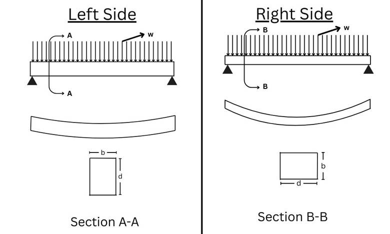
Figure 1 shows two positions of the same beam and their deflections.
On the left and right sides, you can see the position of the beam. On the left side, the longer dimension is placed in the vertical direction, and on the right, in section B-B, the smaller dimension is placed vertically. You can also observe the deflections; the deflection on the right side is greater, and on the left side, it is smaller, which is practically true. This is due to the moment of inertia; both beams are the same, but their placement differs, which changes the area moment of inertia. In Figure 1, the moment of inertia is greater on the left side than on the right side, which causes a smaller deflection on the left side compared to the right side. You might be wondering how the left side moment of inertia is greater than the right side, and how deflection depends on the area moment of inertia. Let’s discuss this.
Our beam in Figure 1 is rectangular so that we will apply the rectangular formula for area moment of inertia calculations. Which is;
$$
I_{\text{xx}} = \frac{b\, d^3}{12}
$$
Whenever we have a rectangular section, this formula will be applied to calculate the moment of inertia. Remember here, “b” is the horizontal dimension, and “d” is the vertical dimension. For example, in Figure 1 on the right side, this formula will become;
$$
I_{\text{xx}} = \frac{d\, b^3}{12}
$$
As shown on the right side of Figure 1, where the horizontal dimension is “d” and the vertical dimension is “b”, the formula includes a cube for “b”. While in equation 1, which is for the left side condition, in which the cube is on “d”. From Figure 1, it is clear that “d” is greater than “b”, which means if the cube is on “d”, then that value will be greater, which is why for the left side, the beam area moment of inertia is greater. (Note: this is all about the x-axis moment of inertia (Ixx), not the y-axis (Iyy))
Now, let’s understand how deflection depends on the area moment of inertia. You should be clear about one thing about deflection, which is that it is inversely proportional to the stiffness. This means that if the stiffness is greater, then the deflection will be smaller in comparison to lower stiffness, which causes higher deflections. Stiffness is basically the multiplication of the area moment of inertia (I) and the elastic constant of the material (E) as shown in the following equation.
$$ \text{Stiffness} = EI $$
Hence, if the area moment of inertia is greater, then the entire stiffness will be greater, which causes lower deflections.
This was a generic introduction to the area moment of inertia. Now, let’s see how to calculate the area moment of inertia of different sections. One thing to note is that this blog will discuss the x-axis area moment of inertia, which refers to the inertia controlling longitudinal deflections, as illustrated in Figure 1. Here, the load acts on the beam, causing it to deflect, resulting in longitudinal deflection.
Area Moment of Inertia of a Rectangle
The area moment of inertia for a rectangular section can be calculated with a simple formula, which is shown here.
$$
I_{\text{xx}} = \frac{b\, d^3}{12}
$$
Here, b is breath, and d is the depth of the section. One thing to remember is that the cube will always lie on the vertical dimension of the section for calculating Ixx. For Iyy, you need to put a cube on the horizontal dimension. This can be seen in Figure 2. If you want a free calculator for area moment of inertia calculations, then click here.
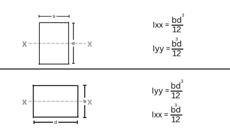
Figure 2 shows rectangular sections and their area moment of inertia.
Area Moment of Inertia of a Circle
The area moment of inertia of a circle can be calculated on its centroidal axis with the following formula.
$$ I_{xx} = I_{yy} = \frac{\pi}{64} d^4 $$
In circular sections, Ixx = Iyy due to symmetry. Here, d is the diameter of the circle. This can also be seen in Figure 3. For a free calculator, click here
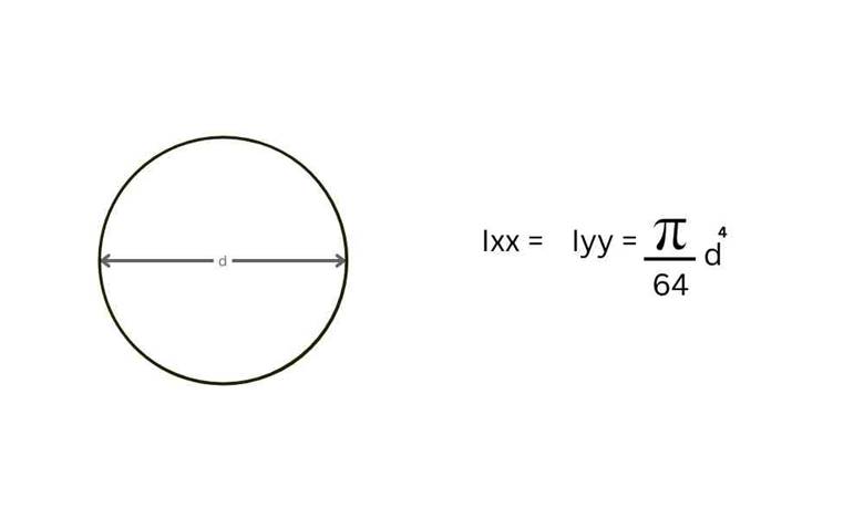
Figure 3 show the moment of inertia of a circle.
Area Moment of Inertia of Hollow Rectangle
Hollow sections resemble a conduit or pipe, as shown in Figure 4. Finding the area moment of inertia of a hollow rectangular section is as simple as that of a complete rectangle. You need to find two area moments of inertia, one for a hollow rectangle and the other for a full rectangle, which includes the hollow part plus the solid part. After finding both area moments of inertia, subtract the hollow moment of inertia from the complete moment of inertia to get the area moment of inertia for your section, which has a solid part.
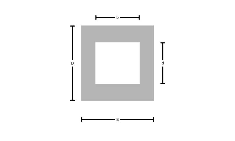
Figure 4 shows hollow rectangle
$$
I_{\text{hollow}} = \frac{b\, d^3}{12}
$$
$$
I_{\text{outer}} = \frac{B\, D^3}{12}
$$
$$
I_{xx} = I_{\text{outer}} – I_{\text{hollow}}
$$
$$
I_{xx} = \frac{B\, D^3}{12} – \frac{b\, d^3}{12}
$$
$$
I_{xx} = \frac{1}{12} \left( B\, D^3 – b\, d^3 \right)
$$
Area Moment of Inertia of a Hollow Circle
To find the area moment of inertia of a hollow circle, we need to follow the same procedure as for the hollow rectangle. Here, we need to find the inner moment of inertia and the outer moment of inertia, then subtract them. You can see a hollow circular section in Figure 5
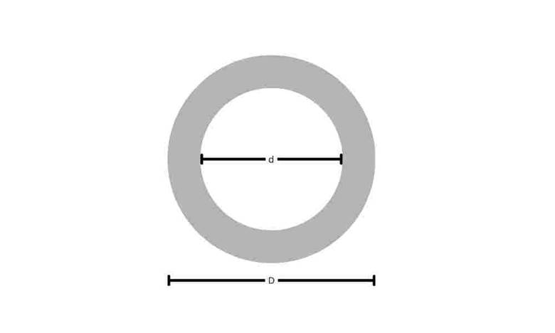
Figure 5 shows hollow rectangle
$$
I_{\text{inner}} = \frac{\pi}{64} d^4
$$
$$
I_{\text{outer}} = \frac{\pi}{64} D^4
$$
$$
I_{xx} = I_{\text{outer}} – I_{\text{inner}}
$$
$$
I_{xx} = \frac{\pi}{64} D^4 – \frac{\pi}{64} d^4
$$
$$
I_{xx} = \frac{\pi}{64} \left( D^4 – d^4 \right)
$$
Area Moment of Inertia of T-section
Finding the moment of inertia of a T-section is a little tricky, as here we need to apply the parallel axis theorem. So first, let’s understand what the parallel axis theorem is. The parallel axis theorem is used to find the moment of inertia of a section on a different axis than the centroidal axis. That new axis must be parallel to the centroidal axis. Let’s understand it with a suitable example, see Figure 6
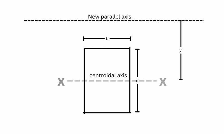
Figure 6 shows the centroidal axis and the parallel axis.
Here, a cross-section is shown with breadth “b” and depth “d”. You need to find the moment of inertia of this section on the new parallel axis, which is parallel to the centroidal axis. If this is the case, then you need to apply the parallel axis theorem. So let’s see how to use the parallel axis theorem.
- First of all, find the moment of inertia of the section on its centroidal axis, which will be,
$$
I_{\text{G}} = \frac{b\, d^3}{12}
$$ - Now find the area of the section. Here, the area is,
$$
\text{Area} = a = {b\,d}
$$ - Now, see the distance between the centroidal axis and the new parallel axis; here, this distance is “y’ ”.
- Now apply the parallel axis theorem formula, which is;
$$
I_{\text{xx at new axis}} = I_G + {a\,y’^2}
$$
Here, Ixx is the moment of inertia of the section at the new axis, and Ig is the moment of inertia of the section of the centroidal axis. At the same time, a is the area, and y’ is the distance between the centroidal axis and the new parallel axis.
- To find the moment of inertia of a T-section, first, we need to find the neutral axis. To find the position of the neutral axis, we need to apply this formula.
$$\bar{y} = \frac{a_1 \times y_1 + a_2 \times y_2}{a_1 + a_2}$$
Here, a1 is the area of the web and a2 is the area of the flange. You can take a1 for the flange and a2 for the web as well.
y1 is the location of the centroidal axis of the web from the bottom, and y2 is the location of the centroidal axis of the flange from the bottom. This can be seen in Figure 8. Andis the location of the neutral axis is from the bottom.
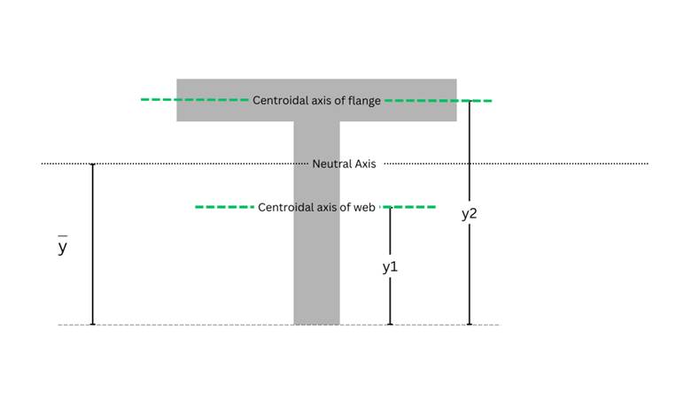
Figure 8 shows the location of the centroidal and neutral axis from the bottom.
$$a_1 = L_w \times T_w = 150 \times 15 = 2250 \; \mathrm{mm}^2$$
$$a_2 = L_f \times T_f = 120 \times 20 = 2400 \; \mathrm{mm}^2$$
$$y_1 = \frac{L_w}{2} = \frac{150}{2} = 75 \; \mathrm{mm}$$
$$y_2 = L_w + \frac{T_f}{2} = 150 + \frac{20}{2} = 160 \; \mathrm{mm}$$
putting all values in the equation,
$$\bar{y} = \frac{2250 \times 75 + 2400 \times 160}{2250 + 2400}$$
$$\bar{y} = 118.87 \;\mathrm{mm}$$
- After finding the neutral axis, we need to calculate the distance between the centroid of the flange and the neutral axis, and from the centroid of the web to the neutral axis. This is because we will first find the gross moment of inertia of the web and flange at their own centroidal axis. Then, using the parallel axis theorem, we will transform these moments of inertia to the section’s neutral axis. Next, we will add the moment of inertia of the flange and web, calculated on the section’s neutral axis, to obtain the total moment of inertia of the T-section. This is illustrated in Figure 9.

Figure 9 shows y’1 and y’2 values
$$y’1 = \bar{y} – y_1 = 118.87 – 75 = 43.87 \text{ mm}$$
$$y’2 = y_2 – \bar{y} = 160 – 118.87 = 41.13 \text{ mm}$$
- Now find the gross moment of inertia of the web and the flange using a simple formula.
$$I_{G\ Flange} = \frac{Lf \times Tf^3}{12} = \frac{120 \times 20^3}{12} = 80,000 \text{ mm}^4$$
$$I_{G\ web} = \frac{Tw \times Lw^3}{12} = \frac{15 \times 150^3}{12} = 42,18,750 \text{ mm}^4$$
- Now, transfer the gross moment of inertia of the flange and web to the neutral axis of the section using the law of parallel axes.
$$I_{flange} = I_{G\ flange} + a_2 \times (y’2)^2$$
$$I_{flange} = 80,000 + (2400) \times (41.13)^2$$
$$I_{flange} = 4,140,024.56 \text{ mm}^4$$
$$I_{web} = I_{G\ web} + a_1 \times (y’1)^2$$
$$I_{web} = 4218750 + 2250 \times (43.87)^2$$
$$I_{web} = 8,549,048.025 \text{ mm}^4$$
- After finding the area moment of inertia of all areas, such as flange and web, on the section’s neutral axis, we need to add all moments of inertia to get the final moment of inertia of the section.
$$I_{xx} = I_{web} + I_{flange}$$
$$I_{xx} = 8,549,048.025 + 4,140,024.56$$
$$I_{xx} = 12,689,072.585 \text{ mm}^4$$
Solution with Free Calculator
This problem can also be solved with our free Area Moment of Inertia Calculator. You can access that by just clicking here.
Area moment of inertia of I beam
The area moment of inertia of an I beam is calculated using the same principle of the parallel axis theorem, which we used in the T-beam.
- First, divide the section into three parts as shown in Figure 10
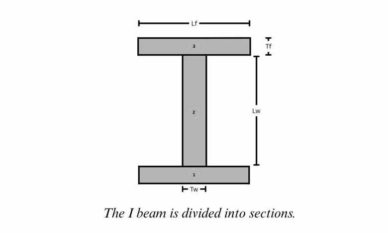
Figure 10 The I beam is divided into sections 1, 2, and 3.
- Secondly, find the neutral axis of the I beam section, which will be at the center due to symmetry, as shown in Figure 11.
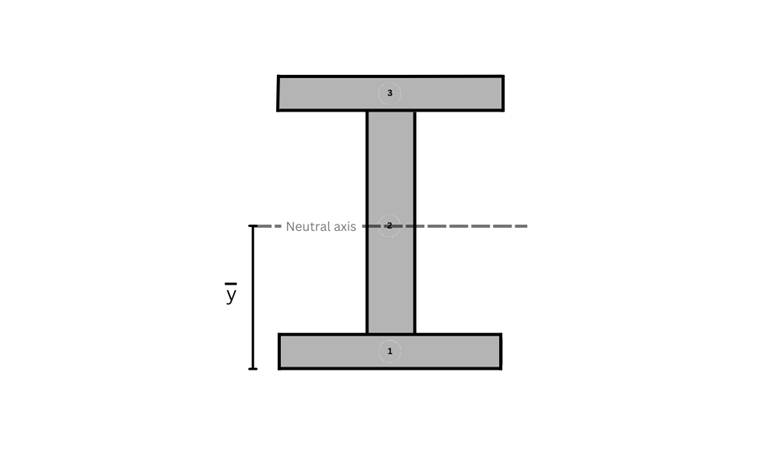
Figure 11 shows the neutral axis of the I beam
- Now find the distance of each part’s neutral axis to the section’s neutral axis, as shown in Figure 12.
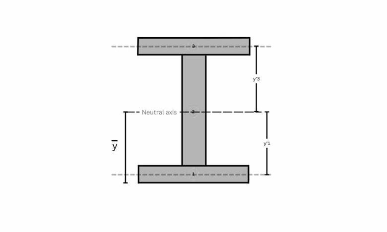
Figure 12 shows y’1 and y’3
Here, you might be wondering why we have y’1 and y’3, but not y’2. You should know that part 2 has the same neutral axis as the entire section; due to this, y’2 = 0.
- Now, calculate the moment of inertia of each part using the simple formula.
$$I_{G\ flange\ 1} = \frac{Lf \times Tf^3}{12}$$
$$I_{G\ flange\ 2} = \frac{Lf \times Tf^3}{12}$$
$$I_{G\ web} = \frac{Tw \times Lw^3}{12}$$
- Now apply parallel axis theorem to transfer the moment of inertia of all parts to the section’s neutral axis, which is explained in T-beam moment of inertia calculations.
$$I_{flange\ 1} = I_{G\ flange\ 1} + a_1 \times (y’1)^2$$
$$I_{flange\ 2} = I_{G\ flange\ 2} + a_3 \times (y’3)^2$$
$$I_{web} = I_{G\ web} + a_2 \times (y’2)^2$$
Here, a1, a2, and a3 are the areas of respective parts, and remember that in the web, y’2 = 0.
- At the end, add all three moments of inertia to get the total moment of inertia of the section.
$$I_{xx} = I_{flange\ 1} + I_{flange\ 2} + I_{web}$$
References
https://calcresource.com/moments-of-inertia-table.html
https://en.wikipedia.org/wiki/List_of_second_moments_of_area